Trim
![]()
The Trim command allows you to trim a sheet body by projecting trimming elements onto the surfaces.
Access
- In the Designer tab, select
 Trim from the drop-down list under the
  Edit Surface
 - In the Surfaces tab, click the icon in the Edit surfaces section of the ribbon.
- Type trim in the Quick Search input field and select Trim from the result list.
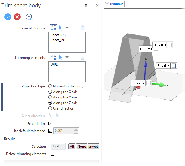
In all cases, this opens the Trim - Options tab which is displayed along with the ribbon containing the Options, Filters and Selection sections. In addition, the Trim sheet body dialog box is displayed. ![]() (See dialog box.)
(See dialog box.)
Procedure
In the following steps, confirmation by Right Mouse click may be required if Multi-select ![]() is active in the Selection options.
is active in the Selection options.
- Select the element(s) to be trimmed.
- Select the reference element(s) to be used for trimming.
- Determine the Projection type.
- Select the Results.
-
Validate, either by a Right Mouse click or by clicking the
 icon in the dialog box.
![]() Note:
Note:
-
Pressing the [W] key of your keyboard allows you to toggle between wireframe and shaded preview display of the entity being created or moved.
Trim Sheet Body - Options
The following options are available in the Trim sheet body dialog box:
Top Toolbar
![]()
![]()
![]()
These two icons at the top of the dialog box allow you to Apply the current values or to Cancel the current function.
Preview generation is Automatic if this option is active in the dialog box menu accessed by clicking on the  icon. If this option is not active, click on the
 ![]() icon. If preview generation is not possible, the icon is greyed out.
icon. If preview generation is not possible, the icon is greyed out.
|
Elements to trim |
This field lists the identifiers of the elements selected for trimming. |
|
Trimming elements |
This field lists the element types used for trimming. The following element types may be used:
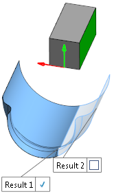
If a face does not intersect the entities to trim and its shape is a planar face, the plane of this face will be used. This is shown in the following example where the green face of the non intersecting block was used for trimming:
|
|
|
For both element selection fields: Clicking on the |
Projection type
The Projection type options determine how the Trimming elements are projected onto the Elements to trim.
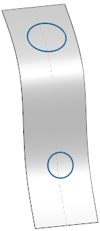
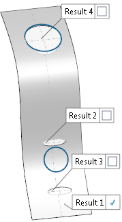
The following sheet body, with two circular trimming elements drawn using a different workplane, is used in the next examples:
|
Normal to the body |
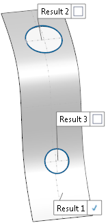
The trimming elements are projected with respect to the normals of the trimmed element. In our example, the result is as follows:
|
|
Along the X axis |
Trimming elements are projected with respect to the X-axis of the active workplane. In our example, this has no effect. |
|
Along the Y axis |
Trimming elements are projected with respect to the Y-axis of the active workplane. In our example, the result is as follows:
|
|
Along the Z axis |
Trimming elements are projected with respect to the Z-axis of the active workplane. In our example, the result is similar to the one obtained with the Normal to the body option. |
|
User direction |
This option activates the Select direction icon allowing you to define your own direction. |
|
Select direction |
Clicking on the |
Extend trim
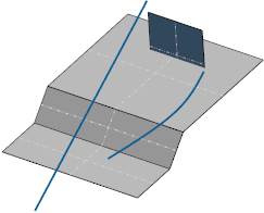
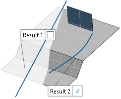
If a trimming element does not completely cut the elements to trim and this option is active, the imprinted cut is tangentially extended to the external border of the trimmed element.
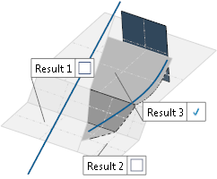
In the following example, the grey sheet body is the element to trim. The blue wireframe elements and the blue face are the trimming elements, as shown in the first image. In the second image, the Extend trim option was not active creating a result where only the straight segment cuts the whole sheet body. In the third image, this option was active extending the cuts:
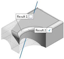
Results
You may select the trimming results to retain directly in graphic area by clicking the check box on the required Result labels (see images above).
The Results section of the dialog box offers the following options:
|
Selection |
This field displays the number of selected results with respect to the number of possible results. |
|
The three buttons alongside this field offer the following possibilities: All: Click this button to select all the results. None: Click this button to deselect all the selected results. Invert: Click this button to invert the current selection. |
|
|
Delete trimming elements |
Activating this option deletes all the wireframe elements used as trimming elements. Faces and workplanes are kept. |
![]() Note:
Note:
It is also possible to trim surfaces contained within a solid body. The result is a sheet body containing the trimmed surfaces:
Information Field
The field at the bottom of the dialog box displays information about missing data, errors or actions.